The following step by step guide will help you in installing Mac OS X 10.6 Snow Leopard as a guest virtual machine in Windows 7. You’ll need to have a system with an Intel processor
which supports hardware virtualization, original OS X Snow Leopard retail disk, VMware Workstation 7 and Windows 7, Vista or XP installed as host operating system. If you meet all these requirements, you can then install OS X Snow Leopard as a VM under Windows and can enjoy the best of both worlds.

Note: We don’t in anyway encourage downloading Apple software via file-sharing / torrent sites and run it in an virtualized environment under Windows. This guide is for informational purposes only. If you like OS X Snow Leopard, Get a Mac.
Step 1: Download and install VMware Workstation 7.
Step 2: Download pre-made modified version of Snow Leopard.vmdk and darwin_snow.iso files required to get this thing to work.
Step 3: Start VMware Workstation and open up “Mac OS X Server 10.6 (experimental).vmx” file which you downloaded in Step 2.
 

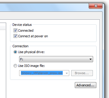
Step 4: Click on”Edit virtual machine settings”, select CD/DVD (IDE) option from left hand side and then and select “Use ISO image file” option. Point it to “darwin_snow.iso” which you downloaded in Step 2.
 

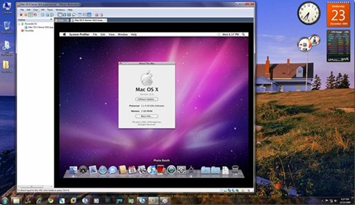
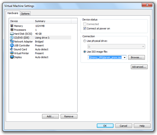
Step 5: Now power on the virtual machine and hit “F8” key. You should now have a screen similar to the one shown below.
Step 6: Now you’ll have to point your virtual machine to OS X Snow Leopard retail DVD instead of “darwin_snow.iso”. To do this, right click on CD/DVD option found in lower right most corner of your VMware window and select settings.


Insert OS X Snow Leopard retail DVD in your DVD drive and select the “Use physical drive” option.
Step 7: Now go back and select “c” option (Boot DVD) from the prompt which you got in Step 5 to boot from the OS X retail DVD. OS X boot screen with Apple logo should now appear. If the boot screen doesn’t appear for you, try booting it in verbose mode by pressing “F8” key after selecting “c” option, and then enter “-v” (without quotes). This will enable the system to boot OS X DVD using verbose mode.


Step 8: Wait for a couple of minutes for the Installation Setup screen to show up. From here on, simply follow the onscreen setup instructions to install OS X Snow Leopard. Make sure you format your virtual hard drive in “Mac OS Extended (Journaled)” format using Disk Utility. Customize your installation with minimum set of printer drivers and language options for a lightweight trouble free installation experience.

Step 9: Once the installation is completed. System will automatically reboot. At this point, close your guest virtual machine and change your CD/DVD option again like you did in Step 2 to point it to “darwin_snow.iso”.

Step 10: Start the virtual machine again. Press “F8” key and select “h” option to “Boot first hard disk”. Voila! Snow Leopard should now be running live under Windows 7!


หลังจากหาข้อมูล PS3 Moeller ก็ทำให้ทราบถึงการ programming ของมัน สามารถทำได้สองทางเหมือน PLC ทั่วไป คือ
1. ผ่าน HandHeld (PRG 3)

2.ผ่านสาย Interface Cable (ZB4-501-UM1) กับ Software (S30-S3)


เมื่อตรวจสอบราคาคร่าวแล้วพบว่าราคาต่างกันมาก จึงเลือกใช้วิธีสองในการ test PS3 ตัวนี้ จึงโหลด S30-S3 (PS3 programming software,MS-DOS) และ คู่มือ S30-S3GB (Moeller PS3 & PS4-100 programming maunul)


PS3 Moeller ตัวนี้ Software เป็น MS-DOS สามารถรันบน Windows OS ได้ 

รายละเอียดของโปรแกรม จะมาอธิบายกันต่อภายหลัง ตอนนี้เรามาหาสายกันก่อนดีกว่า ไม่มีสายก็ไม่สามารถ test อะไรกับมันได้ตอนนี้คงทำอะไรมากไม่ได้ อ่านคู่มือใช้งานก่อนละกัน .................. . . .
กระแส iPhone 4G ในประเทศไทยกะลังมาแรง เชื่อว่านักพัฒนาหลายคนให้มาสนใจงานพัฒนา Application ของ iPhone เพื่อคนไทยมากขึ้น  วันนี้ขอตามกระแสบ้าง เลยหาข้อมูลนำมาเก็บไว้ ใน Blog แหล่งนี้เผื่อจะมีคนสนใจบ้าง จะได้ช่วยเป็นกำลังใจในการเก็บข้อมูล

คำถามที่เกิดขึ้น ณ ตอนนี้ " SDK iPhone ต้องใช้เครื่อง Mac ในการพัฒนาหรือ? " 
iPhone เป็น ผลิตภัณฑ์ของ Apple  เพราะงั้นคงหนีไม่พ้นที่จะต้องใช้เครื่อง Mac 
จบประเด็นเลยทีนี้ สำหรับคนที่คิดว่าจะต้องซื้อเครื่อง Mac เพื่อมาพัฒนา Application ของ iPhone หลายคนคงหมดหวัง
เพราะโอกาสซื้อเครื่อง Mac ใหม่คงเป็นไปไม่ได้ (เหมือนกัน......T T....ลาก่อน iPhone ช่างห่างไกลกันเหลือเกิน)

งั้นมาเก็บความรู้เกี่ยวกับ iPhone ดีกว่า (ไม่ได้ใช้พัฒนาขอคุยกับคนอื่นรู้เรื่องละกัน)
OS ของ iPhone มีชื่อว่า iOS ( ไอ อ๊อดดดดดด) ปัจจุบันเป็น vesion 4 ละ
เครื่องมือที่ใช้ในการพัฒนา Application ชื่อ XCode  (เอ็ก โครต)  สามารถดาวโหลดได้ที่นี่แต่ต้องสมัครสมาชิคกับทาง Apple ก่อน (ฟรี แต่ขนาด File 3 Gb เท่านั้น)
เขียนด้วยภาษา Objective-C


อ่านไปอ่านมาเจอเวป น่าสนใจอยู่ เริ่มต้นกับการเขียนโปรแกรมบน iPhone ก็เจอเลยมีเครื่อง Mac ก็ใช่ว่าจะได้พัฒนาเจ้า iPhone
เพราะมีข้อจำกัดอยู่ว่า ต้องเป็น OS X Snow Leopard 10.6 ขึ้นไป ใครที่เป็นรุ่นต่ำกว่านี้ก็อดเช่นกัน แต่แล้วก็ยิ้มได้เพราะในเวปมีบอก
ไว้ว่ามี Mac OS X บน PC ธรรมดา งั้นไปหาอากู๋กัน
งี้ต้องลองไว้สำเร็จแล้วจะมาบอกวิธีกัน....


และแล้วก็ได้ไปเอาเจ้า PS3 กลับมา หน้าตาอย่างที่เห็นเลย แต่สภาพกับไม่ใช่ (รูปมาจากว่า http://www.applied-automation.com/products/klockner/ps3.shtml ) แล้วน้ำหนักมันก็หนักใช่ย่อย กว่าจะแกะมันออกมาจากตู้ได้ 
พอได้มันมาก็หารีบ PDF ที่เคยโหลดไว้ จะดูว่าอะไรเป็นอะไรบ้าง  (PS 3-AC-110      Compact PLC, 16DI, 8 Relays, 4AI, 1AO, RTC, 110Vac)


ส่วนประกอบต่างๆของ PS3 แบ่งออกเป็นทั้งหมด 16 ส่วน ดังนี้
1. 24 V/160 mA Power Supply of the Digital INPUT 
2. Address Coding
3. I/O status LEDS แบ่งเป็น 2 แถว 4 ชุด  
     - 2 ชุดบน เป็น INPUT status LEDS (16DI)
     - ชุดล่างด้านซ้าย เป็น OUTPUT status LEDS (8 relay)
     - ชุดสุดท้าย เป็น SYSTEM status LEDS
4. Battery
5. SUCUnet bus terminating resistor
6. 24 V DC Digital INPUT
7. 10 kHz Counter INPUT
8. SUCOnet Interface
9. SUCOnet and PRG Interface
10. Digital OUTPUT
11. Front Plate and Panel
12.PS3-DC-...24 V DC Power Supply of the Digital OUTPUT
13. PS3-AC/8-...110/220 V AC
14. PS3-DC...24 V DC Main Terminal
15.Only PS3 DC-Short-circuit and Overload Switch
16.Analog INPUT,Analog OUTPUT 0-10 V DC

เมื่อรู้รายละเอียดตามข้างบน จึงเริ่มทดสอบ
 - นำ Power Supply 110 V AC มาต่อตำแหน่งที่ 13 แล้ว ก็ลุ้นๆ สักพัก LED Power (ข้างตำแหน่งที่  2) บน PS3 ก็ติด
- สักพัก LED Run ก็กระพริบอยู่สักพักแล้วก็ ค้าง 
- ปิด Power Supply 110 V 
สรุปผลว่า ภาคการจ่ายไฟของเจ้า PS3 ตัวอย่างยังเป็นปกติดี
แล้วก็มานั่งคิดต่อว่า เจ้า PS3 ยังหลงเหลือความจำของมันอยู่หรือป่าว(Program)
แต่ยังไม่รู้ทำไง จึงต้องหาข้อมูลต่อไป .....


 " PS3 Moeller .. .. .. .. ... .ครับ ครับ "
" PS3 Moeller ??? คืออะไร ไม่เข้า อะไร ยังไง งง เอะ(...)"  
" ช่วย Test  ให้หน่อยว่ายังใช้งานอยู่ได้ หรือ "
" ครับ..........!!! "
แล้วแล้ว งานก็เข้า Test อะไร มันคือ อะไร PS3 (Play Station 3 ???) แล้ว Moeller คือไร (Moeller) ทำไงเอาไงดี สงสัยต้องพึ่ง อากู๋

และแล้วก็ได้รู้  นั่นไง PLC นั่นเอง อากู๋ เข้าเวปโหลด PDF มาดู มาอ่าน แล้วก็เริ่มเข้าใจ หน้าตามันเป็นแบบนี้นี่เอง

งั้นมาดูรายละเอียดของเจ้า PS3 Moeller ดีกว่า

  - เป็น PLC Compact สัญชาติ Germany ถูกแทนด้วยรุ่นใหม่ PS4 ในปี 1995 แต่ยังคงมีเครื่องลงเหลืออยู่ทั่วโลก ( !!! 15 ปี อยู่มาได้ถึงทุกวันนี้ อึดพอตัวนะเนี่ย)
  -จำนวน INPUT / OUTPUT เปลี่ยนตามจำนวนรุ่น
PS 3-DC : Compact PLC, 16DI, 16DO, 4AI, 1AO, RTC, 24Vdc
PS 3-DC-EE : Compact PLC, 16DI, 16DO, 4AI, 1AO, RTC, EEPROM, 24Vdc
PS 3-AC : Compact PLC, 16DI, 8 Relays, 4AI, 1AO, RTC, 230Vac
PS 3-AC-EE : Compact PLC, 16DI, 8 Relays, 4AI, 1AO, RTC, EEPROM, 230Vac
PS 3-AC-110 : Compact PLC, 16DI, 8 Relays, 4AI, 1AO, RTC, 110Vac
PS 3-8 : Compact PLC, 8DI, 8 Relays, 230Vac

 - Programming ผ่านทาง Hand Held (PRG 3) หรือ สาย Cable (ZB4-501-UM1) กับ โปรแกรม Sucosoft S30-S3 (For dos) (โปรแกรมบน Dos ซะด้วย)
ได้ข้อมูลเรียบร้อย หน้าที่ต่อไปต้องไปตรวจสภาพของเจ้า PS3.....(รอวันที่จะได้เจอกัน....^^)
หลายคนคงเกิดความสงสัยเกี่ยวกับการนับจำนวน Tag ของ GENESIS32 วันนี้มีตัวอย่างการนับมาให้ดู 
อ้างอิงจาก การนับ Tag ของ GENESIS32

ปกติการนับ Tag ของ SCADA ส่วนใหญ่ จะนับ Tag แบบ FIX Tag Count คือไม่สนใจว่า ขณะ Runtime นั้นติดต่ออยู่กับ Tag ใดบ้างจึงจำเป็นต้องระบุจำนวน Tag ต่อ License เป็นจำนวนมาก


แต่การนับ Tag ของ GENESIS32 นั้น เป็นแบบ RUNTIME Tag Count คือ ว่าขณะ Runtime นั้นมีการติดต่อกับ OPC Tag ตัวใดอยู่บ้างนับตามที่มีการติดต่อ ซึ่งเป็นคุณลักษณะของ OPC  to the Core

ตัวอย่าง

FIX Tag Count RUNTIME Tag Count
ระบบ graphic แสดงผลจากสัญญาณ300 300
ระบบ alarm จากสัญญาณกลุ่มเดียวกับ graphic
    Limit
    - HIHI                 300
    - HI                     300
    - LOW               300
    - LOWLOW     300
    Digital(ON/OFF)  300
    Derivative           300
    Rate of Change   300
300*7= 2100 300
ระบบ trend จากสัญญาณกลุ่มเดียวกับ graphic300 300
Expression และ Variable อื่น ๆ 100ไม่จำกัด
รวมจำนวน Tag 2800300

สมมุติสัญญาณทุกตัวใช้พร้อมกัน RUNTIME Tag Count จะนับจำนวน Tag 300 Tag เพราะเป็นกลุ่มเดียวกัน
ซึ่งเทียบได้กับ FIX Tag Count  ถึงอย่างน้อย 2800 Tag

นอกจากนั้นในกรณีที่สัญญาณมาจาก DI หรือ DO เราสามารถรับค่า Register มาเป็นกลุ่ม เช่น Word จาก OPC Server ได้ นั้นหมายถึงว่า OPC tag 1 ตัวจะเท่ากับ 16 DI หรือ 16 DO เลยทีเดียว ทำให้เราสามารถประหยัดงบประมาณในการซื้อไลเซนส์ของแท็กไปได้มหาศาลเลยครับ จากนั้นเราสามารถระบุ Bit ที่ต้องการใช้งานจาก GENEISIS32 โดยตรง
How to make your own blogger templates! This question was revolving in my mind since last few months. Initially I started my blogging with blogspot and I used to search for new cool templates. No doubt, there are several beautiful and professional blogger templates available today. But a template can never touch your imaginations. Everyone thinks in a different way likewise they also want their template to be different.

Making your own template will provide you a lots of scope and space to act your thoughts. You can choose the width, height, no of columns and a lots of other things. But there are no such tutorials available that can guide us. So, I thought of coming up with a post which will have A to Z of making a blogger template.

Note that we are going to make HTML template. This is not a XML template. XML template is a bit more difficult to make. Well, I will cover that too, but later. For now we will learn the method of making a HTML blogger template. For this, you have to switch on to classic template and then add the code. There will be no widgets, you have to add all codes (adsense/HTML/JavaScript) manually. Still, there are several advantages of CSS templates.

Step 1 : Choose your CSS style :
There are thousands of free CSS templates available on net today. You can search and choose any of them. But just to make your life easier, I am providing few free CSS template sources. Check out them and choose one of your choice
Open Source Web Design
 
Step 2 : Changing the title tags of your template :

After downloading your template, open yourtemplate.html with notepad or any of those html editors. Find <title> and </title> at the top of the template. Now put the below code between <title> and </title>.
<ItemPage><a href=”<$BlogURL$>”></ItemPage>

<$BlogTitle$>

<ItemPage></a></ItemPage>
Now it should look like the below screenshot.
make your own blogger templates

Step 3 : Changing Header Of Template :
Now find <body> tag and below there must be something like <div id=”header”>. Copy the below code and paste it there.
<ItemPage><a href=”<$BlogURL$>”></ItemPage><$BlogTitle$>

<ItemPage></a></ItemPage>
Look at the screen shot below to get the idea.
how to make blogger templates
Step 4 : Putting Blogger Body Codes To Template :
This is the most important part. Body codes contain important things like blog posts, comments, post titles, post dates etc. <div id> for this section changes from template to template, so you need to get a good html editor like Adobe’s Dream Weaver to do editing. You may find a lots of <div id> codes there. You have to delete them all and then paste the blogger body code there. Get blogger post body codes here.

For an example the below screenshot is having <div id=”main”>. You can have “My Body” or “Contents” etc.
how to make your own blogger template

Step 5 : Showing Recent Posts :
Classic templates are not widget ready, I’ve told it before. So, we have to add everything mnually within the template code. Now, the most important thing that all we want is a recent posts tab, showing latest posts on our blog. Let’s add it.
It’s a simple code that you need to add between <ul> and </ul> tags . There should be two or four <ul> tags present in your template. Now you decide the location where you want this recent posts tab to show up. After selecting one location, delete all the <li> codes present between <ul> and </ul> tags. Then paste the below code:
 
<BloggerPreviousItems>
<li><a href=”<$BlogItemPermalinkURL$>”><$BlogPreviousItemTitle$></a></li> 
 
</BloggerPreviousItems>
 
Now we added recent posts section to our template.

Step 6 : Showing Archive :
Archieves section is very essential in a template. This works as a sitemap for search engines and hence having this will increase your SEO values. At the mean time it gives your users the freedom to navigate. It’s a must have for all the templates.
Find a tag starts with <ul> and ends with </ul>, delete all the <li> codes present inside it and paste the below code.

<MainOrArchivePage><ul><BloggerArchives>
<li><a href=”<$BlogArchiveURL$>”><$BlogArchiveName$></a></li>
</BloggerArchives></ul></MainOrArchivePage>
 
We are almost done now!

Step 7 : Adding Other Things ( Adsense,Stats,Entrecard etc.) :
Repeat the same thing that you were doing for adding recent posts or archieves. Then add your adsense code or HTML code there. Hit save button and publish.

Step 8 : Editing Footer :
Footer tag is always labeled as <div id = footer>. Find this link and add your anchor link text or whatever you want there. And now we are completely done.
Congrats!  Now you can make your own blogspot templates easily.
Virtual private LAN service (VPLS) is a way to provide Ethernet based multipoint to multipoint communication over IP/MPLS networks. It allows geographically dispersed sites to share an Ethernet broadcast domain by connecting sites through pseudo-wires. The technologies that can be used as pseudo-wire can be Ethernet over MPLS, L2TPv3 or even GRE. There are two IETF standards track RFCs (RFC 4761 and RFC 4762) describing VPLS establishment.
VPLS is a virtual private network (VPN) technology. In contrast to L2TPv3, which allows only point-to-point layer 2 tunnels, VPLS allows any-to-any (multipoint) connectivity.
In a VPLS, the local area network (LAN) at each site is extended to the edge of the provider network. The provider network then emulates a switch or bridge to connect all of the customer LANs to create a single bridged LAN.

Mesh establishment

Since VPLS emulates a LAN, full mesh connectivity is required. There are two methods for full mesh establishment for VPLS: using BGP and using Label Distribution Protocol (LDP). The "control plane" is the means by which provider edge (PE) routers communicate for auto-discovery and signaling. Auto-discovery refers to the process of finding other PE routers participating in the same VPN or VPLS. Signaling is the process of establishing pseudo-wires (PW). The PWs constitute the "data plane", whereby PEs send customer VPN/VPLS traffic to other PEs.
With BGP, one has auto-discovery as well as signaling. The mechanisms used are very similar to those used in establishing Layer-3 MPLS VPNs. Each PE is configured to participate in a given VPLS. The PE, through the use of BGP, simultaneously discovers all other PEs in the same VPLS, and establishes a full mesh of pseudo-wires to those PEs.
With LDP, each PE router must be configured to participate in a given VPLS, and, in addition, be given the addresses of other PEs participating in the same VPLS. A full mesh of LDP sessions is then established between these PEs. LDP is then used to create an equivalent mesh of PWs between those PEs.
An advantage to using PWs as the underlying technology for the data plane is that in case of failure, traffic will automatically be routed along available backup paths in the service provider's network. Failover will be much faster than could be achieved with e.g. Spanning Tree Protocol (STP). VPLS is thus a more reliable solution for linking together Ethernet networks in different locations than simply connecting a WAN link to Ethernet switches in both locations.
VPLS has significant advantages for both service providers and customers. Service providers benefit because they can generate additional revenues by offering a new Ethernet service with flexible bandwidth and sophisticated service level agreements (SLAs). VPLS is also simpler and more cost effective to operate than a traditional service. Customers benefit because they can connect all of their sites to an Ethernet VPN that provides a secure, high speed and homogenous network. Moreover, VPLS provides a logical next step in the continuing evolution of Ethernet from a 10 Mbps shared LAN protocol to a multi-Gbps global service.

Label stack

VPLS MPLS packets have a two-label stack. The outer label is used for normal MPLS forwarding in the service provider's network. If BGP is used to establish the VPLS, the inner label is allocated by a PE as part of a label block. If LDP is used, the inner label is a virtual circuit ID assigned by LDP when it first established a mesh between the participating PEs. Every PE keeps track of assigned inner label, and associates these with the VPLS instance.

Ethernet emulation

PEs participating in a VPLS-based VPN must appear as an Ethernet bridge to connected customer edge (CE) devices. Received Ethernet frames must be treated in such a way as to ensure CEs can be simple Ethernet devices.
When a PE receives a frame from a CE, it inspects the frame and learns the CE's MAC address, storing it locally along with LSP routing information. It then checks the frame's destination MAC address. If it is a broadcast frame, or the MAC address is not known to the PE, it floods the frame to all PEs in the mesh.
Ethernet does not have a time to live (TTL) field in its frame header, so loop avoidance must be arranged by other means. In regular Ethernet deployments, Spanning Tree Protocol is used for this. In VPLS, loop avoidance is arranged by the following rule: A PE never forwards a frame received from a PE, to another PE. The use of a full mesh combined with split horizon forwarding guarantees a loop-free broadcast domain.

Scalability

VPLS is typically used to link a large number of sites together. Scalability is therefore an important issue that needs addressing.

Hierarchical VPLS

VPLS requires a full mesh in both the control and data planes; this can be difficult to scale. For BGP, the control plane scaling issue has long been addressed, through the use of route reflectors (RRs). RRs are extensively used in the context of Internet routing, as well as for several types of VPNs. To scale the data plane for multicast and broadcast traffic, there is work in progress to use point-to-multipoint LSPs as the underlying transport.
For LDP, a method of subdividing a VPLS VPN into two or three tiered hierarchical networks was developed. Called hierarchical VPLS (HVPLS), it introduces a new type of MPLS device: the multi-tenant unit (MTU) switch. This switch aggregates multiple customers into a single PE, which in turn needs only one control and data plane connection into the mesh. This can significantly reduce the number of LDP sessions and LSPs, and thus unburden the core network, by concentrating customers in edge devices.

MAC addresses

Since VPLS links multiple Ethernet broadcast domains together, it effectively creates a much larger broadcast domain. Since every PE must keep track of all MAC addresses and associated LSP routing information, this can potentially result in a large amount of memory being needed in every PE in the mesh.
To counter this problem, sites may use a router as the CE device. This hides all MAC addresses on that site behind the CE's MAC address.
PE devices may also be equipped with content-addressable memory (CAM), similar to high-end Ethernet switches.
An alternative mechanism is using MAT (MAC Address Translation). However, at the time of writing this, there aren't vendors providing MAT functionality.

PE auto-discovery

In a VPLS-based VPN with a large number of sites, manually configuring every participating PE does not scale well. If a new PE is taken into service, every existing PE needs to have its configuration adjusted to establish an LDP session with the new PE. Standardization work is in progress to enable auto-discovery of participating PEs. Three implementations are being worked on:

LDP

The LDP method of PE auto-discovery is based on that used by the Label Distribution Protocol to distribute labels across P and PE routers within a single autonomous system.

BGP


The BGP method of PE auto-discovery is based on that used by Layer-3 MPLS VPNs to distribute VPN routes among PEs participating in a VPN. The BGP4 Multi-Protocol (BGP-MP) extensions are used to distribute VPN IDs and VPN-specific reachability information. Since IBGP requires either a full mesh of BGP sessions or the use of a route reflector, enabling the VPN ID in a participating PEs existing BGP configuration provides it with a list of all PEs in that VPN. Note that this method is for auto-discovery alone; LDP is still used for signaling. The method of establishing VPLS with BGP described above accomplishes both auto-discovery and signaling.

RADIUS


This method requires ALL PEs to be configured with one or more RADIUS servers to use. When the first CE router in a particular VPLS VPN connects to the PE, it uses the CE's identification to request authentication from the RADIUS server. This identification may be provided by the CE, or may be configured into the PE for that particular CE. In addition to a username and password, the identification string also contains a VPN name, and an optional provider name.
The RADIUS server keeps track of all PEs that requested authentication for a particular VPN, and returns a list of them to the PE requesting authentication. The PE then establishes LDP sessions to every PE in the list.
A virtual private network (VPN) is a network that uses a public telecommunication infrastructure and their technology such as the Internet, to provide remote offices or individual users with secure access to their organization's network. It aims to avoid an expensive system of owned or leased lines that can be used by only one organization. The goal of a VPN is to provide the organization with the same secure capabilities but at a much lower cost.
It encapsulates data transfers between two or more networked devices not on the same private network so as to keep the transferred data private from other devices on one or more intervening local or wide area networks. There are many different classifications, implementations, and uses for VPNs.

History

Until the end of the 1990s the computers in computer networks connected through very expensive leased lines and/or dial-up phone lines. It could cost thousands of dollars for 56kbps lines or tens of thousands for T1 lines, depending on the distance between the sites.
Virtual Private Networks reduce network costs because they avoid a need for many leased lines that individually connect to the Internet. Users can exchange private data securely, making the expensive leased lines redundant.[1].
VPN technologies have myriad protocols, terminologies and marketing influences that define them. For example, VPN technologies can differ in:
  • The protocols they use to tunnel the traffic
  • The tunnel's termination point, i.e., customer edge or network provider edge
  • Whether they offer site-to-site or remote access connectivity
  • The levels of security provided
  • The OSI layer they present to the connecting network, such as Layer 2 circuits or Layer 3 network connectivity
Some classification schemes are discussed in the following sections.

Security Mechanisms

Secure VPNs use cryptographic tunneling protocols to provide confidentiality by blocking intercepts and packet sniffing, allowing sender authentication to block identity spoofing, and provide message integrity by preventing message alteration.
Secure VPN protocols include the following:

Authentication

 unnel endpoints must authenticate before secure VPN tunnels can establish.
User-created remote access VPNs may use passwords, biometrics, two-factor authentication or other cryptographic methods.
Network-to-network tunnels often use passwords or digital certificates, as they permanently store the key to allow the tunnel to establish automatically and without intervention.

Routing

Tunneling protocols can be used in a point-to-point topology that would theoretically not be considered a VPN, because a VPN by definition is expected to support arbitrary and changing sets of network nodes. But since most router implementations support software-defined tunnel interface, customer-provisioned VPNs often are simply defined tunnels running conventional routing protocols.
On the other hand provider-provided VPNs (PPVPNs), need to support coexisting multiple VPNs, hidden from one another, but operated by the same service provider.

PPVPN Building blocks

Depending on whether the PPVPN runs in layer 2 or layer 3, the building blocks described below may be L2 only, L3 only, or combine them both. Multiprotocol Label Switching (MPLS) functionality blurs the L2-L3 identity.
RFC 4026 generalized the following terms to cover L2 and L3 VPNs, but they were introduced in RFC 2547.[6]
Customer edge device. (CE)
a device at the customer premises, that provides access to the PPVPN. Sometimes it's just a demarcation point between provider and customer responsibility. Other providers allow customers to configure it.
Provider edge device (PE)
A PE is a device, or set of devices, at the edge of the provider network, that presents the provider's view of the customer site. PEs are aware of the VPNs that connect through them, and maintain VPN state.
Provider device (P)
A P device operates inside the provider's core network, and does not directly interface to any customer endpoint. It might, for example, provide routing for many provider-operated tunnels that belong to different customers' PPVPNs. While the P device is a key part of implementing PPVPNs, it is not itself VPN-aware and does not maintain VPN state. Its principal role is allowing the service provider to scale its PPVPN offerings, as, for example, by acting as an aggregation point for multiple PEs. P-to-P connections, in such a role, often are high-capacity optical links between major locations of provider.

User-visible PPVPN services

 This section deals with the types of VPN considered in the IETF; some historical names were replaced by these terms.

OSI Layer 1 services

Virtual private wire and private line services (VPWS and VPLS)

In both of these services, the provider does not offer a full routed or bridged network, but provides components to build customer-administered networks. VPWS are point-to-point while VPLS can be point-to-multipoint. They can be Layer 1 emulated circuits with no data link structure.
The customer determines the overall customer VPN service, which also can involve routing, bridging, or host network elements.
An unfortunate acronym confusion can occur between Virtual Private Line Service and Virtual Private LAN Service; the context should make it clear whether "VPLS" means the layer 1 virtual private line or the layer 2 virtual private LAN.

OSI Layer 2 services

Virtual LAN

A Layer 2 technique that allows for the coexistence of multiple LAN broadcast domains, interconnected via trunks using the IEEE 802.1Q trunking protocol. Other trunking protocols have been used but have become obsolete, including Inter-Switch Link (ISL), IEEE 802.10 (originally a security protocol but a subset was introduced for trunking), and ATM LAN Emulation (LANE).
Virtual private LAN service (VPLS)
Developed by IEEE, VLANs allow multiple tagged LANs to share common trunking. VLANs frequently comprise only customer-owned facilities. The former[clarification needed] is a layer 1 technology that supports emulation of both point-to-point and point-to-multipoint topologies. The method discussed here extends Layer 2 technologies such as 802.1d and 802.1q LAN trunking to run over transports such as Metro Ethernet.
As used in this context, a VPLS is a Layer 2 PPVPN, rather than a private line, emulating the full functionality of a traditional local area network (LAN). From a user standpoint, a VPLS makes it possible to interconnect several LAN segments over a packet-switched, or optical, provider core; a core transparent to the user, making the remote LAN segments behave as one single LAN.[7]
In a VPLS, the provider network emulates a learning bridge, which optionally may include VLAN service.
Pseudo wire (PW)
PW is similar to VPWS, but it can provide different L2 protocols at both ends. Typically, its interface is a WAN protocol such as Asynchronous Transfer Mode or Frame Relay. In contrast, when aiming to provide the appearance of a LAN contiguous between two or more locations, the Virtual Private LAN service or IPLS would be appropriate.
IP-only LAN-like service (IPLS)
A subset of VPLS, the CE devices must have L3 capabilities; the IPLS presents packets rather than frames. It may support IPv4 or IPv6.

OSI Layer 3 PPVPN architectures

This section discusses the main architectures for PPVPNs, one where the PE disambiguates duplicate addresses in a single routing instance, and the other, virtual router, in which the PE contains a virtual router instance per VPN. The former approach, and its variants, have gained the most attention.
One of the challenges of PPVPNs involves different customers using the same address space, especially the IPv4 private address space[8]. The provider must be able to disambiguate overlapping addresses in the multiple customers' PPVPNs.
BGP/MPLS PPVPN
In the method defined by RFC 2547, BGP extensions advertise routes in the IPv4 VPN address family, which are of the form of 12-byte strings, beginning with an 8-byte Route Distinguisher (RD) and ending with a 4-byte IPv4 address. RDs disambiguate otherwise duplicate addresses in the same PE.
PEs understand the topology of each VPN, which are interconnected with MPLS tunnels, either directly or via P routers. In MPLS terminology, the P routers are Label Switch Routers without awareness of VPNs.
Virtual router PPVPN
The Virtual Router architecture,[9][10] as opposed to BGP/MPLS techniques, requires no modification to existing routing protocols such as BGP. By the provisioning of logically independent routing domains, the customer operating a VPN is completely responsible for the address space. In the various MPLS tunnels, the different PPVPNs are disambiguated by their label, but do not need routing distinguishers.
Virtual router architectures do not need to disambiguate addresses, because rather than a PE router having awareness of all the PPVPNs, the PE contains multiple virtual router instances, which belong to one and only one VPN.

Plaintext Tunnels

Some virtual networks may not use encryption to protect the data contents. While VPNs often provide security, an unencrypted overlay network does not neatly fit within the secure or trusted categorization. For example a tunnel set up between two hosts that used Generic Routing Encapsulation (GRE) would in fact be a virtual private network, but neither secure nor trusted.
Besides the GRE example above, native plaintext tunneling protocols include Layer 2 Tunneling Protocol (L2TP) when it is set up without IPsec and Point-to-Point Tunneling Protocol (PPTP) when it does not use Microsoft Point-to-Point Encryption (MPPE).

Trusted delivery networks

Trusted VPNs do not use cryptographic tunneling, and instead rely on the security of a single provider's network to protect the traffic.
From the security standpoint, VPNs either trust the underlying delivery network, or must enforce security with mechanisms in the VPN itself. Unless the trusted delivery network runs among physically secure sites only, both trusted and secure models need an authentication mechanism for users to gain access to the VPN.

VPNs in mobile environments

Mobile VPNs handle the special circumstances when an endpoint of the VPN is not fixed to a single IP address, but instead roams across various networks such as data networks from cellular carriers or between multiple Wi-Fi access points.[14] Mobile VPNs have been widely used in public safety, where they give law enforcement officers access to mission-critical applications, such as computer-assisted dispatch and criminal databases, as they travel between different subnets of a mobile network.[15] They are also used in field service management and by healthcare organizations,[16] among other industries.
Increasingly, mobile VPNs are being adopted by mobile professionals and white-collar workers who need reliable connections.[16] They allow users to roam seamlessly across networks and in and out of wireless-coverage areas without losing application sessions or dropping the secure VPN session. A conventional VPN cannot survive such events because the network tunnel is disrupted, causing applications to disconnect, time out[14], or fail, or even cause the computing device itself to crash.[16]
Instead of logically tying the endpoint of the network tunnel to the physical IP address, each tunnel is bound to a permanently associated IP address at the device. The mobile VPN software handles the necessary network authentication and maintains the network sessions in a manner transparent to the application and the user.[14] The Host Identity Protocol (HIP), under study by the Internet Engineering Task Force, is designed to support mobility of hosts by separating the role of IP addresses for host identification from their locator functionality in an IP network. With HIP a mobile host maintains its logical connections established via the host identity identifier while associating with different IP addresses when roaming between access networks.

Reference : Virtual_private_network


A virtual LAN, commonly known as a VLAN, is a group of hosts with a common set of requirements that communicate as if they were attached to the same broadcast domain, regardless of their physical location. A VLAN has the same attributes as a physical LAN, but it allows for end stations to be grouped together even if they are not located on the same network switch. Network reconfiguration can be done through software instead of physically relocating devices.

To physically replicate the functions of a VLAN, it would be necessary to install a separate, parallel collection of network cables and switches/hubs which are kept separate from the primary network. However unlike a physically separate network, VLANs must share bandwidth; two separate one-gigabit VLANs using a single one-gigabit interconnection can both suffer reduced throughput and congestion. It visualizes VLAN behaviors (configuring switch ports, tagging frames when entering VLAN, lookup MAC table to switch/flood frames to trunk links, and untagging when exit from VLAN.)

Uses 

VLANs are created to provide the segmentation services traditionally provided by routers in LAN configurations. VLANs address issues such as scalability, security, and network management. Routers in VLAN topologies provide broadcast filtering, security, address summarization, and traffic flow management. By definition, switches may not bridge IP traffic between VLANs as it would violate the integrity of the VLAN broadcast domain.
This is also useful if someone wants to create multiple Layer 3 networks on the same Layer 2 switch. For example, if a DHCP server (which will broadcast its presence) is plugged into a switch it will serve any host on that switch that is configured to get its IP from a DHCP server. By using VLANs you can easily split the network up so some hosts won't use that DHCP server and will obtain link-local addresses, or obtain an address from a different DHCP server.
Virtual LANs are essentially Layer 2 constructs, compared with IP subnets which are Layer 3 constructs. In an environment employing VLANs, a one-to-one relationship often exists between VLANs and IP subnets, although it is possible to have multiple subnets on one VLAN or have one subnet spread across multiple VLANs. Virtual LANs and IP subnets provide independent Layer 2 and Layer 3 constructs that map to one another and this correspondence is useful during the network design process.
By using VLANs, one can control traffic patterns and react quickly to relocations. VLANs provide the flexibility to adapt to changes in network requirements and allow for simplified administration.

History

 In 1984, Dr. W David Sincoskie was attempting to develop Voice over Ethernet for Bellcore. His early estimates figured that a successful network would need roughly a terabit of bandwidth to function. Since at this time routing was slow and complex, the solution was to make an Ethernet-based system which would scale. The problem with a traditional Ethernet-switched network was that it operates as a spanning-tree and suffers from the fact that the roots prove to be bottlenecks. Since the speeds being dealt with would total 1 terabit, and 100Mb ethernet was still theoretical, current ethernet systems could not be used and another solution was needed. Another downside to a traditional Ethernet-based solution was that there was always a single point of failure. Dr. Sincoskie hypothesized that the bridging algorithm could be applied to spanning trees in order to create smaller segregated networks which would reduce the bandwidth needed at each root in the tree.[1] In order to allow this to happen, a tree number would need to be inserted into each packet, either implicitly or through the creation of an additional field. This additional field is what is now known in the Ethernet frame as the 802.1Q header, or the VLAN tag. Dr. Sincoskie referred to it as the multitree bridge. With the help of Dr. Chase Cotton, the two created and refined the algorithms (called the Extended Bridge Algorithms for Large Networks) necessary to make the system feasible and published their results in the 1988 IEEE Network.[2]

Implementation

A basic switch not configured for VLANs will either have VLAN functionality disabled, or will have it permanently enabled with what is known as a default VLAN which simply contains all ports on the device as members.
Configuration of the first custom VLAN port group usually involves subtracting ports from the default VLAN, such that the first custom group of VLAN ports is actually the second VLAN on the device, apart from the default VLAN. The default VLAN typically has an ID of 1.
If a VLAN port group were to only exist on the one device, all ports that are members of the VLAN group only need to be "untagged". It is only when the port group is to extend to another device that tagging is used. For communications to occur from switch to switch, an uplink port needs to be a tagged member of every VLAN on the switch that uses that uplink port, including the default VLAN.
Some switches either allow or require a name be created for the VLAN, but it is only the VLAN group number that is important from one switch to the next.
Where a VLAN group is to simply pass through an intermediate switch via two pass-through ports, only the two ports need to be a member of the VLAN, and are tagged to pass both the required VLAN and the default VLAN on the intermediate switch.
Management of the switch requires that the management functions be associated with one of the configured VLANs. If the default VLAN were deleted or renumbered without moving the management to a different VLAN first, it is possible to be locked out of the switch configuration, requiring a forced clearing of the device configuration to regain control.
Switches typically have no built-in method to indicate VLAN port members to someone working in a wiring closet. It is necessary for a technician to either have management access to the device to view its configuration, or for VLAN port assignment charts or diagrams to be kept next to the switches in each wiring closet. These charts must be manually updated by the technical staff whenever port membership changes are made to the VLANs.
Remote configuration of VLANs presents several opportunities for a technician to accidentally cut off communications and lock themselves out of the devices they are attempting to configure. Actions such as subdividing the default VLAN by splitting off the switch uplink ports into a separate new VLAN can suddenly cut off all remote communication, requiring the technician to physically visit the device in the distant location to continue the configuration process.

Motivation

In a legacy network, users were assigned to networks based on geography and were limited by physical topologies and distances. VLANs can logically group networks so that the network location of users is no longer so tightly coupled to their physical location. Technologies able to implement VLANs are:

Protocols and design

The protocol most commonly used today in configuring virtual LANs is IEEE 802.1Q. The IEEE committee defined this method of multiplexing VLANs in an effort to provide multivendor VLAN support. Prior to the introduction of the 802.1Q standard, several proprietary protocols existed, such as Cisco's ISL (Inter-Switch Link) and 3Com's VLT (Virtual LAN Trunk). Cisco also implemented VLANs over FDDI by carrying VLAN information in an IEEE 802.10 frame header, contrary to the purpose of the IEEE 802.10 standard.
Both ISL and IEEE 802.1Q tagging perform "explicit tagging" - the frame itself is tagged with VLAN information. ISL uses an external tagging process that does not modify the existing Ethernet frame, while 802.1Q uses a frame-internal field for tagging, and so does modify the Ethernet frame. This internal tagging is what allows IEEE 802.1Q to work on both access and trunk links: frames are standard Ethernet, and so can be handled by commodity hardware.
The IEEE 802.1Q header contains a 4-byte tag header containing a 2-byte tag protocol identifier (TPID) and a 2-byte tag control information (TCI). The TPID has a fixed value of 0x8100 that indicates that the frame carries the 802.1Q/802.1p tag information. The TCI contains the following elements:
  • Three-bit user priority
  • One-bit canonical format indicator (CFI)
  • Twelve-bit VLAN identifier (VID)-Uniquely identifies the VLAN to which the frame belongs
The 802.1Q standard can create an interesting scenario on the network. Recalling that the maximum size for an Ethernet frame as specified by IEEE 802.3 is 1518 bytes, this means that if a maximum-sized Ethernet frame gets tagged, the frame size will be 1522 bytes, a number that violates the IEEE 802.3 standard. To resolve this issue, the 802.3 committee created a subgroup called 802.3ac to extend the maximum Ethernet size to 1522 bytes. Some network devices that do not support a larger frame size will process the frame successfully but may report these anomalies as a "baby giant."[3]
Inter-Switch Link (ISL) is a Cisco proprietary protocol used to interconnect multiple switches and maintain VLAN information as traffic travels between switches on trunk links. This technology provides one method for multiplexing bridge groups (VLANs) over a high-speed backbone. It is defined for Fast Ethernet and Gigabit Ethernet, as is IEEE 802.1Q. ISL has been available on Cisco routers since Cisco IOS Software Release 11.1.
With ISL, an Ethernet frame is encapsulated with a header that transports VLAN IDs between switches and routers. ISL does add overhead to the packet as a 26-byte header containing a 10-bit VLAN ID. In addition, a 4-byte CRC is appended to the end of each frame. This CRC is in addition to any frame checking that the Ethernet frame requires. The fields in an ISL header identify the frame as belonging to a particular VLAN.
A VLAN ID is added only if the frame is forwarded out a port configured as a trunk link. If the frame is to be forwarded out a port configured as an access link, the ISL encapsulation is removed.
Early network designers often configured VLANs with the aim of reducing the size of the collision domain in a large single Ethernet segment and thus improving performance. When Ethernet switches made this a non-issue (because each switch port is a collision domain), attention turned to reducing the size of the broadcast domain at the MAC layer. Virtual networks can also serve to restrict access to network resources without regard to physical topology of the network, although the strength of this method remains debatable as VLAN Hopping [4] is a common means of bypassing such security measures.
Virtual LANs operate at Layer 2 (the data link layer) of the OSI model. Administrators often configure a VLAN to map directly to an IP network, or subnet, which gives the appearance of involving Layer 3 (the network layer). In the context of VLANs, the term "trunk" denotes a network link carrying multiple VLANs, which are identified by labels (or "tags") inserted into their packets. Such trunks must run between "tagged ports" of VLAN-aware devices, so they are often switch-to-switch or switch-to-router links rather than links to hosts. (Note that the term 'trunk' is also used for what Cisco calls "channels" : Link Aggregation or Port Trunking). A router (Layer 3 device) serves as the backbone for network traffic going across different VLANs.

Cisco VLAN Trunking Protocol (VTP)

On Cisco Devices, VTP (VLAN Trunking Protocol) maintains VLAN configuration consistency across the entire network. VTP uses Layer 2 trunk frames to manage the addition, deletion, and renaming of VLANs on a network-wide basis from a centralized switch in the VTP server mode. VTP is responsible for synchronizing VLAN information within a VTP domain and reduces the need to configure the same VLAN information on each switch.
VTP minimizes the possible configuration inconsistencies that arise when changes are made. These inconsistencies can result in security violations, because VLANs can cross connect when duplicate names are used. They also could become internally disconnected when they are mapped from one LAN type to another, for example, Ethernet to ATM LANE ELANs or FDDI 802.10 VLANs. VTP provides a mapping scheme that enables seamless trunking within a network employing mixed-media technologies.
VTP provides the following benefits:
  • VLAN configuration consistency across the network
  • Mapping scheme that allows a VLAN to be trunked over mixed media
  • Accurate tracking and monitoring of VLANs
  • Dynamic reporting of added VLANs across the network
  • Plug-and-play configuration when adding new VLANs
As beneficial as VTP can be, it does have disadvantages that are normally related to the spanning tree protocol (STP) as a bridging loop propagating throughout the network can occur. Cisco switches run an instance of STP for each VLAN, and since VTP propagates VLANs across the campus LAN, VTP effectively creates more opportunities for a bridging loop to occur.
Before creating VLANs on the switch that will be propagated via VTP, a VTP domain must first be set up. A VTP domain for a network is a set of all contiguously trunked switches with the same VTP domain name. All switches in the same management domain share their VLAN information with each other, and a switch can participate in only one VTP management domain. Switches in different domains do not share VTP information.
Using VTP, each Catalyst Family Switch advertises the following on its trunk ports:
  • Management domain
  • Configuration revision number
  • Known VLANs and their specific parameters

Establishing VLAN memberships

The two common approaches to assigning VLAN membership are as follows:
  • Static VLANs
  • Dynamic VLANs
Static VLANs are also referred to as port-based VLANs. Static VLAN assignments are created by assigning ports to a VLAN. As a device enters the network, the device automatically assumes the VLAN of the port. If the user changes ports and needs access to the same VLAN, the network administrator must manually make a port-to-VLAN assignment for the new connection.
Dynamic VLANs are created through the use of software. With a VLAN Management Policy Server (VMPS), an administrator can assign switch ports to VLANs dynamically based on information such as the source MAC address of the device connected to the port or the username used to log onto that device. As a device enters the network, the device queries a database for VLAN membership. See also FreeNAC which implements a VMPS server.

Protocol Based VLANs 

In a protocol based VLAN enabled switch, traffic is forwarded through ports based on protocol. Essentially, the user tries to segregate or forward a particular protocol traffic from a port using the protocol based VLANs; traffic from any other protocol is not forwarded on the port. For example, if you have connected a host, pumping ARP traffic on the switch at port 10, connected a Lan pumping IPX traffic to the port 20 of the switch and connected a router pumping IP traffic on port 30, then if you define a protocol based VLAN supporting IP and including all the three ports 10, 20 and 30 then IP packets can be forwarded to the ports 10 and 20 also, but ARP traffic will not get forwarded to the ports 20 and 30, similarly IPX traffic will not get forwarded to ports 10 and 30.

VLAN Cross Connect

 VLAN Cross Connect (CC) is a mechanism used to create Switched VLANs, VLAN CC uses IEEE 802.1ad frames where the S Tag is used as a Label as in MPLS . IEEE does not recommend this model as it violated the basic bridging principles.

Reference : Virtual_LAN